Train System Modeling
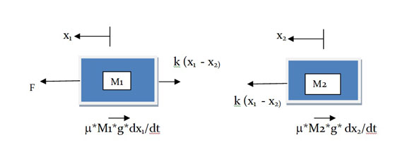
The system can be represented by these free body diagrams. The force $F$ is in the positive $x$ direction (going to the left). The displacements of the engine and the wagon are given by $x_1$ and $x_2$ respectively. Consequently, their velocities are given by ${dx_1}/ {dt}$ and ${dx_2}/ {dt}$ respectively. The frictional forces acting on them (in the negative $x$ direction, i.e., to the right) are given by $μ.M1.g{dx_1}/ {dt}$ and $μ.M2.g{dx_2}/ {dt}$, respectively, where $g$ is the gravitational force. Clearly, the spring force $k (x_1-x_2)$ acts in the negative $x$ direction for the engine but it acts in the positive $x$ direction for the wagon. So, there are three forces working on the engine and two forces working on the wagon.